
Creating a 3D game asset is not all that different from creating a physical object in the real world. The skills and labor required don’t line up perfectly (you’re more likely to develop carpal tunnel than lose a finger, just as one example), but there’s more overlap there than one might think.
This series of posts will go through our workflow for creating 3D assets from the ground up. I’ll mention the tools and services we use in each step, but won’t get too bogged down in technical specifics. Instead I will focus on the thought process and theory behind each step, which can be applied to any pipeline or workflow.
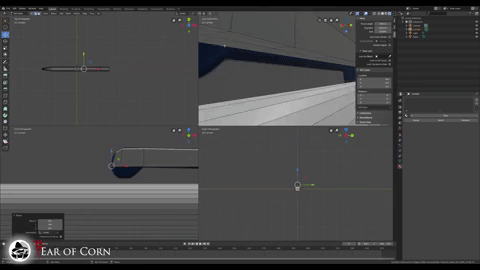
To kick things off, we will look at modeling a 3D object. We use Blender for this step of the process, and the deliverable will be one or several FBX files with all the data we need for our next steps.
Research
Before we even open our 3D software, the first and arguably most critical step is to research what exactly it is we want to make. We have a lot of flexibility and artistic license when creating things to populate our game’s world, but it’s still important to keep real world dimensions and design standards in mind, since inconsistencies across objects can be very noticeable when playing the game.
The specific things to research vary wildly from item to item, but here is a general checklist we always compare against before we start modeling:
- Dimensions: Make sure the object is the correct size relative to the booth and, more importantly, other objects.
- Era-appropriate: A coffee maker from 2015 looks a lot different than one from 1985.
- Feasibility: If we find a reference for an object with complex geometry or that relies on unnecessary physics simulation, it’s probably not ideal for our own sanity and for the ultimate performance of the game.
Modeling
Once we’ve completed our research and gathered some reference photos and dimensions, it’s time to open up Blender and get to work. We’ve done a deep dive into Blender in a previous post, so definitely check that out if you are interested in the program specifics.
On a higher level, the goal here is to create an approximation of the real-world object while keeping the geometry as simple as possible. 3D modeling for games and real-word manufacturing share a key limitation: complex geometry is more expensive. In physical manufacturing, it costs time and money to get a person (or machine) capable of creating an object to match a complex spec. In computer modeling, that complexity results in more processing power required to render the virtual object.
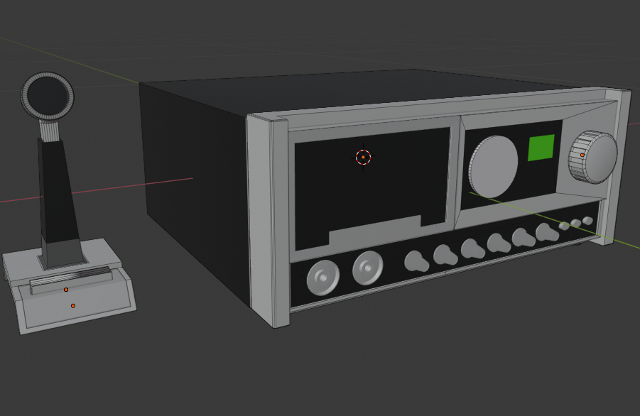
So while we never want to cut corners in noticeably detrimental ways, some smart planning can optimize the model’s geometry while maintaining the standard of realism we strive for. Working on a model with lots of complex, beveled edges? Maybe save the higher resolution bevels for the most prominent edges facing the player. Have a really cool design carved into the side of an object? Don’t model it, leave the surface flat and add the design to the material with a normal map (we’ll get to this in a later post!).
By thinking in terms of optimization before and while we model, we can end up with something game-ready the first time, rather than trying to optimize an ultra-complex model after the fact.
UV Mapping
UV Mapping is cool because there isn’t really a clear parallel to real-world manufacturing. To explain it simply, 3D models are made up of 2D faces. When applying a 2D texture to a 3D model, a program needs data to know which parts of the texture image should map to which faces. This data is provided in the form of a UV map.
A UV map is essentially a 2D plane where faces of a 3D model can be laid out and arranged on a 2D image. If you’re curious to learn more, you can check out this great post that explores it in a bit more depth.
In practice, our approach to UV mapping generally involves trying to pack as many faces as possible into a single 2048×2048 texture while trying to maintain consistent texture resolution and avoiding too many obvious “seams” when a texture should flow seamlessly between faces.

It sort of creates a three way juggling act, because trying to accomplish one goal often comes at the expense of others. For example, shrinking the faces on the UV map allows you to pack more in, but that results in lower texture resolution for those faces, which might be an issue.
At the end of the day, it’s really more of an art than a science, and something that just begins to come a little more naturally with time. It’s maybe not the most flashy work, but I truly think that getting even high resolution UVs evenly mapped to a complex mesh is one of the most satisfying feelings in this entire process.

Conclusion
Once our model is complete and the UVs are mapped, it’s time to export our FBX file(s). An FBX file is readable by Unreal Engine and contains all the geometry and UV data we just spent all that time perfecting in Blender, so it’s a great universal exchange format for just about any 3D modeling workflow.
Our rule of thumb is that any piece that will be animated in-engine will be its own FBX. As these FBX files will contain all the data we need for the remainder of the process, we are done with Blender for now!
Next up we will be looking at graphic design, so stay tuned for another post next week!